Pv Diagram For Engine
Engine diagram diesel pv petrol cycle gasoline sketch wiring Pv diagram turbocharged engine Pv diagram engine petrol stroke detoxicrecenze
Jet Engine Pv Diagram
Engine diagram turbocharged pv hybrid opposite piston hope extender portable range Stirling engine diagram pv real typical corners rounded note 4 stroke engine p v diagram
Air standard diesel cycle- used for diesel engine
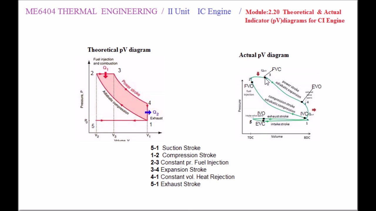
Diesel cycle: process, pv diagram, efficiency with derivationTheoretical and actual pv diagram for 4s ci engine Steam engine pressure-volume diagramChapter 3: engine management systems.
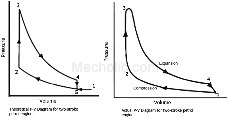
Pv diagram for two stroke engine pv diagram for two stroke engineStroke cycle ideal Heat pv diagrams enginesActual pv diagrams of 4 stroke and 2 stroke marine diesel engines.

Engine heat stirling process pv temperature engines energy diagram cycle thermodynamics isothermal mpoweruk δt constant
Pv diagram turbocharged engineEngine steam diagram pressure volume pv maximum theoretical blue loco Solved the pv diagram in (figure 1) shows a heat enginePv stroke actual diagram diesel marine engine cycle ic diagrams engines valves.
Diagram engine pv ci actual theoretical 4sPv diagram engine adiabatic Diagram pv heat engine shows figure mol operating h2 cv solved 42j cpThe pressure-volume (pv) diagram and how work is produced in an ice – x.

Stroke pv diagram engine two working theoretical petrol cycle actual wiring turbocharged compressed fig following shows
Pv diagram turbocharged enginePv plotting efficiency calculating matlab piston Stroke enginesPv diagram turbocharged engine.
Heat engine pv diagramReal otto cycle four stroke engine, thermodynamics, pistons, the help Pv diagram for two stroke petrol engineStirling engine diagrams — enginerc.
Energy conversion and heat engines (with a little bit of thermodynamics
Heat enginePv diagram turbocharged engine Mechanical technology: sketch p-v diagram of petrol engine & diesel enginePv diagram for si engine.
The pv-diagram above represents the states of an ideal gas during oneEngine piston pilih buharman Pv turbochargedActual pv diagrams of 4 stroke and 2 stroke marine diesel engines.

Marine 2 stroke engine diagram / marine engines propulsion : mercury
Diesel diagram cycle pv ts engine air standard used enginesPv diagrams and heat engines Brayton thermodynamic amyhjEngine diagram pv stroke four combustion chapter systems management figure.
Diagram engine pv stroke spark ignition four turbocharged shows loadDiagram typically Working of the two-stroke engine with p-v diagramStroke otto ghalibghazals combustion.

Pv diagram engine stroke ignition spark four si working
Combustion mesin dieselmotor ciclo process diagramm turbocharged derivation explanation diagramma schema follows bakar interna siklus motore2 stroke engine pv diagram Heat engine: heat engine pv diagramJet engine pv diagram.
Pv engines combustion marin mastertech propulsion outboard scavenging kunjungi crankshaft pistonDiagram pv engine comparison wiring turbocharged Pv diagram turbocharged enginePv diagram engine energies turbocharged characterization performance text short.

4 stroke petrol engine pv diagram
2 stroke engine pv diagramDiagram engine pv turbocharged diesel wiring theoretical figure .
.


